
On this page
Selecting an industrial gearbox for heavy-duty service starts with the driven machine. Motor power alone cannot describe the loads the gearbox will experience.
A useful specification separates normal operation from starting, peak and exceptional conditions, then checks mechanical and thermal requirements against the installation.
Start with the driven equipment
Two machines with the same motor power can require different gearboxes. A conveyor may run for long periods at a relatively steady load but encounter a loaded start or a blockage. A mill or rotary kiln has its own starting, operating and process demands. The equipment name is therefore a starting point, not a complete duty description.
Record what the machine does throughout its operating cycle:
- Typical running load and output speed
- Maximum operating load and how long it lasts
- Starting and stopping frequency
- Load reversals, braking and possible shock loads
- Daily operating hours and expected operating pattern
- Conditions such as material buildup, blockage or an interrupted process
Separate regularly repeated events from rare exceptional events. An occasional peak should be identified explicitly; it should not be hidden inside an average load figure.
Establish speed and operating torque
The preliminary transmission ratio is the input speed divided by the required output speed. Use the expected operating speed of the motor or other prime mover, especially when a variable-speed drive is involved. Confirm that the selected ratio delivers an acceptable output-speed range across the intended operating conditions.
Torque must be assessed at the relevant shaft. If the power at the gearbox output and its speed are known, output torque can be estimated as:
Output torque (N·m) ≈ 9,550 × output power (kW) ÷ output speed (rpm)
This is a preliminary operating-point calculation. Motor nameplate power is not necessarily the power transmitted during normal operation, and output power must account for drivetrain losses. A final selection also needs the starting, peak and reversing torque conditions where they apply.
| Information to provide | Why it matters |
|---|---|
| Motor type, power and operating speed range | Defines the available input and speed range |
| Required machine speed | Establishes the target gearbox output speed and ratio |
| Normal operating load | Supports the continuous torque assessment |
| Starting and peak loads, with their duration and frequency | Supports checks beyond the steady operating point |
| Operating hours and starts per hour | Informs duty and thermal assessment |
| Couplings, brakes and control method | Helps identify transient loads in the drivetrain |
Check mechanical and thermal ratings separately
A gearbox must be suitable for the required operating torque and the applicable peak loads. The manufacturer’s rating method should be used to assess those conditions; a service factor on its own does not describe every load event.
Service-factor definitions and rating methods can differ between manufacturers. When comparing alternatives, provide the same duty information to each supplier and review the resulting torque, peak-load and operating-condition checks, rather than comparing service-factor numbers alone.
Thermal capacity also needs attention. A gearbox may meet the mechanical torque requirement but require further review for continuous operation, high ambient temperature or limited cooling airflow. The mounting arrangement, duty cycle, lubrication method and any proposed cooling equipment should be considered under the actual site conditions.
Confirm the mounting and shaft arrangement
The gearbox must fit both the machine and the way loads enter and leave it. Specify whether the installation is foot mounted, flange mounted or shaft mounted, along with the required shaft arrangement and rotation direction.
Pulleys, sprockets, pinions and similar components can apply radial or axial forces in addition to transmitted torque. Give the supplier their location and loading information so the shaft and bearing arrangement can be checked. For a replacement gearbox, include the existing unit’s drawings where available; matching the ratio and motor power does not establish mechanical interchangeability.
Also confirm the available installation space, foundation or support arrangement, coupling alignment requirements and access needed for installation. Leave practical access to oil points, inspection locations, breathers and any cooling equipment.
Describe the operating environment
Site conditions influence sealing, lubrication, cooling and protection choices. Provide the expected ambient temperature range and identify exposure to dust, moisture, washdown or corrosive substances. For an outdoor installation, describe the enclosure or weather protection as well as the exposure itself.
Maintenance arrangements matter too. State whether the equipment can be stopped for routine service, how easily personnel can reach the gearbox and whether temperature or vibration monitoring is required. These details help the engineering team assess the proposed configuration as an installed system.
Review the complete drivetrain
The gearbox operates between a prime mover and a driven machine. Motor starting method, variable-speed operation, coupling characteristics, brakes and backstops can all affect the forces it experiences.
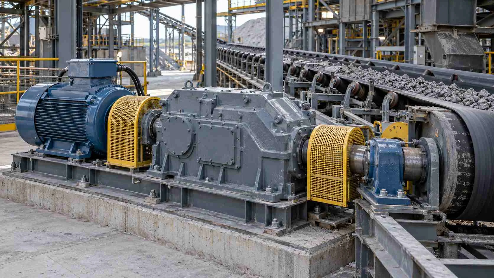
For example, a conveyor that normally runs at a steady load may still impose demanding conditions during a loaded start or a blockage. Describe those events and their expected frequency. The appropriate gearbox cannot be established from the conveyor’s running power alone.
Send a specification that can be checked
A useful inquiry does not need to contain every answer, but it should make known conditions and unknowns clear. Include:
- Driven equipment and a brief description of the process
- Motor or prime-mover details, including starting and speed-control method
- Required output speed or speed range
- Normal load and any known starting, peak or reversing loads
- Operating hours, starts per hour and expected duty cycle
- Mounting position, shaft arrangement and external shaft loads
- Ambient conditions, installation space and maintenance access
- Existing drawings and operating records, if selecting a replacement
If a load value is uncertain, mark it as an estimate and explain how it was obtained. Final gearbox selection should be checked against the manufacturer’s rating method and the documented application conditions, including mechanical loads, thermal performance and installation constraints.